TL;DR
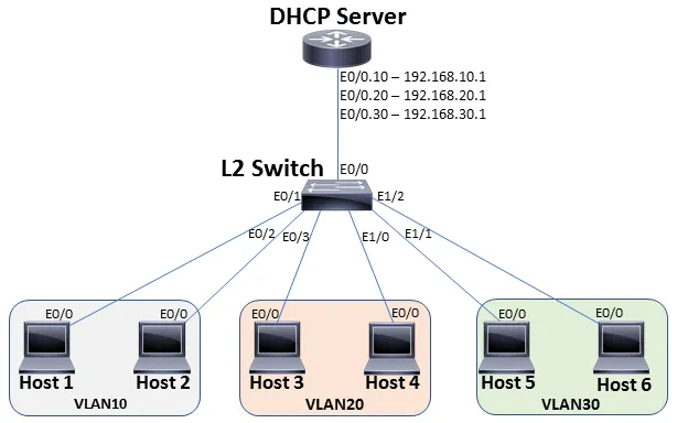
Ever heard about router on a stick? It literally does not mean that a router should be placed on a stick. It means that a router and switch are connected via a single physical interface configured as 802.1q trunk. The switch has multiple VLANs configured and the router is taking care of the routing between the different VLANs. To make it understand better, the following topology will be considered.
There are two objectives:
- All the hosts in different VLANs should receive an IP Address from the DHCP server.
- All the hosts in different VLANs should be reachable from each other.
Routing between VLANs (also called Inter-VLAN routing) is performed by the router connected to the trunk port on the switch. Three VLANs are configured on the switch – VLAN 10, 20 and 30. We will start initially with the switch configuration.
interface Ethernet0/0switchport trunk encapsulation dot1qswitchport mode trunkinterface vlan10exitinterface vlan20exitinterface vlan30exitVLAN10 – Hosts 1 and 2interface Ethernet0/1switchport access vlan 10switchport mode access!interface Ethernet0/2switchport access vlan 10switchport mode accessVLAN20 – Hosts 3 and 4interface Ethernet0/3switchport access vlan 20switchport mode access!interface Ethernet1/0switchport access vlan 20switchport mode accessVLAN30 – Hosts 5 and 6interface Ethernet1/1switchport access vlan 30switchport mode access!interface Ethernet1/2switchport access vlan 30switchport mode access
By default, all the VLANs on the switch are allowed on the trunk interface as confirmed by below output.
Switch#show interfaces trunkPort Mode Encapsulation Status Native vlanEt0/0 on 802.1q trunking 1Port Vlans allowed on trunkEt0/0 1-4094Port Vlans allowed and active in management domainEt0/0 1,10,20,30Port Vlans in spanning tree forwarding state and not prunedEt0/0 1,10,20,30
In order to receive an IP Address from the DHCP Server, a Cisco router is configured as a DHCP Server. A DHCP pool is defined on the Cisco router which assigns IP Addresses to the hosts from the pool defined. In order to configure multiple networks in the DHCP pool, the use of secondary command is mandatory. Otherwise, the router only accepts the last network command while erasing the previous ones.
ip dhcp pool MANY_VLAN network 192.168.10.0 255.255.255.0 network 192.168.20.0 255.255.255.0 secondary network 192.168.30.0 255.255.255.0 secondary
In order to establish a trunk link with the switch, sub-interfaces for each VLAN are required to be configured on the router. An IP address is assigned to each sub-interface and the encapsulation is set to 802.1q. Keep in mind that the 802.1Q VLAN ID should match the VLAN IDs of the switch. For example,
encapsulation dot1Q <1-4094> <– Only 10,20,30 should only be configured under the sub-interfaces as these are the only VLANs configured on the switch.
The sub-interface can be defined any value in the range of <0-4294967295>. For example,
interface Ethernet0/0.<0-4294967295> <– This does not have to match the VLAN ID on the switch. However, the recommended way is to keep the sub-interface same as the dot1Q to remember easily.
interface Ethernet0/0no ip address!interface Ethernet0/0.10encapsulation dot1Q 10ip address 192.168.10.1 255.255.255.0!interface Ethernet0/0.20encapsulation dot1Q 20ip address 192.168.20.1 255.255.255.0!interface Ethernet0/0.30encapsulation dot1Q 30ip address 192.168.30.1 255.255.255.0
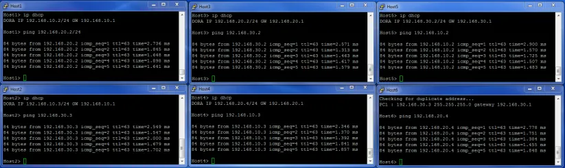
Once the router and switch configurations are completed, let’s move to each host one-by-one and enter the command ip dhcp to fetch an IP Address from the DHCP Server. The below picture shows the IP Addresses assigned to each hosts with reachability to all the other hosts in different VLANs.